Wednesday, March 11, 2009

RFID activated phone system

I feel most hobbyists make things that are useful. I tend to like to make prototypes. To me that's what I like about the iobridge so much. I can prototype things very quickly that in the past would have taken me a long time to create. I was able to make my phone system in the morning before heading off to school. I tend to think about usability more than most engineers, and as a biomedical engineer I like to think about products for physicians, patients, and the elderly. When I was an undergrad I had an idea for a phone system for the elderly. Yes there are phones with large buttons and few features, but they are often very ugly and you still have to remember the phone number. My idea was to create a phone that would dial the desired number based on placing a picture on or near the phone. In essence the device would work like the many iphone apps out there that allow you to call a person by pressing their picture on your phone. My dialer could be this advanced, with a touch screen and the whole nine yards, but I really liked the idea of physically doing something. Here's my prototype:


One note about the video. This has nothing to do with an iphone. The system will connect any two phones.

To create the RFID activated phone dialer I used:

The RFID reader is very simple to use and is easliy connected to an arduino. Code to run the reader can be found on the arduino website. For my purposes this did almost everything I needed it to do. My only change was to put a delay after reading a card. This eliminated multiple reads if you swiped the card by the reader slowly. Since the iobridge JSON object stores the serial data for a period of time, I also added a line of code to change the stored serial data after my javascript had a chance to read the RFID tag. If I didn't do this then the phone dialer javascript would keep making phone calls.

Dialer without cover

The arduino sends the RFID info to the iobridge via a connection between the TX pin on the arduino and the serial smart board. The dialing is done on my home computer/server that is running a bit of javascript. The javascript compares the RFID code and dials the appropriate phone number. This is the heart of the javascript I have running back on my computer.
function testNumber(numtocall) {

if (numtocall == "RFIDTAG1") {
// RFIDTAG1 is the unique tag
window.location="tel:XXXXXXXXXX";
// XXXXXXXXXX is the phone number to call
}
else if (numtocall == "RFIDTAG2") {
// RFIDTAG2 is the unique tag
window.location="tel:XXXXXXXXXX";
// XXXXXXXXXX is the phone number to call

// ... repeat for each tag you have
}

function checkNumber() {
$.getJSON("http://www.iobridge.com/api/feed/key=YYYYYYYYYYYY&callback=?",
// YYYYYYYYYYYY is the key for your iobridge
function (data) {
testNumber(data.module.channels[3].LastSerialInput); // 3 is the 4th channel on the iobridge (0-3)
});
}

$(document).ready(function() {
checkNumber();
setInterval("checkNumber()", 10000);
});

The script checks the feed of my ioBridge every 10 seconds and then parses the JSON object. The LastSerialInput is then compared to the RFID tags I have in the script. If a match is found then the call is placed.

To place the call I used a tel:URL. This works like a mailto:URL, but instead of activating your email program to start and email it activated a phone program to dial a number. The program I use all the time for this is Vocito. It works with Google Voice. I use google voice and Vocito all the time so I didn't think twice before picking this combo as my dialing method. For those of you without google voice, I am sure you could activate a phone call with numerous other programs and systems.

ioBridge Serial Smart Board Tutorial

My little tutorial about controlling your lights with an ioBridge was well received by the guys over at ioBridge.com so I thought I would make another tutorial. This time I wanted to go over a really powerful tool ioBridge just released, the serial smart board. The smart board allows an iobridge to send and receive serial signals. In this tutorial I will be suppling a serial signal from my arduino microcontroller. Here's the video tutorial. Keep reading after the video for more details.


Let's start with the arduino sketch. Like I said in the video, this is a really simple circuit that is probably one of the first people make. One of the best arduino tutorials around is the one by the fine folks at ladaya.net, and the circuit I used can be found in their 5th lesson. The only change to the sketch I used is to insert the corresponding Serialprintln("I turned it on"); and Serialprintln("I turned it off); Into the loops that turn the LED on and off. Since ladaya.net covers the arduino portion of the tutorial so well, I'll jump to the ioBridge section.

ioBridge serial smart board


After building the circuit and programing your arduino, power down your iobridge. Plug in the serial smart board to an open channel and then power your iobridge back up. Whenever plugging in a new smart board you need to be sure to restart your iobridge so it will detect the new board.

Connect the grounds of your iobridge and arduino circuit. If you haven't done so at this time load your sketch onto the arduino board. Finally connect the TX pin (pin 1) to the RX pin on your iobridge serial smart board. If you make this connection before uploading your sketch you will probably get an error.

Head over to the iobridge.com website and log in. Click on the module tab and then select the module you plugged the serial smart board into. Change the appropriate channel to the "serial" mode and save the change.


Select serial as the mode


The iobridge will now "listen" for data. If you go ahead and press the button on your circuit the text should pop up in box just under where you selected the serial mode. If you see garbage instead of the text you are expecting, some of your settings are probably off. Make sure your baud rates are the same on the arduino and iobridge. Also make sure you have the right pacing and inversion mode set for your setup.

I'm using:
baud rate = 9600
pacing = 0
Signal mode = inverted


Channel listening for serial data


Now that everything is set up correctly go to the widgets tab and create a new widget. Select "Monitor Serial Messages (Real-time)". This is the widget you use when you want the iobridge to "read" serial data. The other two serial setting "write" serial data. Then click your module, and then select the channel you installed the serial smart board onto. Now you've got a serial monitor. As with all widgets you can copy the provided code to any webpage or just view the results from your iobridge dashboard.


Completed widget


In my video I just viewed it from the dashboard. Back in the widget's tab, click the plus next to the widget you just created to add the widget to your dashboard. Next, click on the widget dashboard. You should see your widget here. It is currently listening for data. If you push the push button then serial data will be sent from the arduino to the iobridge and be displayed on the dashboard.


Widget after being added to the dashboard

Saturday, December 6, 2008

Controlling your lights with an ioBridge Module


Controlling my house lights with the ioBridge module is something that really excites me. It's so simple I didn't want to write about it first since it doesn't give the module justice for how powerful it really is. The ioBridge module is able to control my lights or anything else that plugs into an electrical outlet via x10 modules.

x10 and home automation has been around since the 1970's, so controlling your house's lights isn't new. There is software out there to run on your computer to control your x10 setup. That being said, ioBridge's x10 interface is one of the best looking and easiest to use I've ever seen. Plus, with no setup I can control my lights over the internet. What I really like is how controllable it is. Since the iobridge widgets spits out javascript I can embed in a webpage, I can make my controller look and act just like I want it to.


Step by step instructions for controlling a lamp


I set up x10 controllers in my living room, bedroom, and for my christmas lights. I wanted to be able to turn on my lights when I was away from home or once I was already in bed. I can leave my room a bit messy sometimes so it's key for me to leave a light on as I get into bed. I don't want to kick a random shoe or something and break a toe.

The setup is almost as easy as just plugging everything in, so I wanted to talk a little more this time about the ioBridge web interface and how to embedd their javascript into your webpage.

The setup:
ioBridge module
ioBridge x10 smart board
x10 controllers


ioBridge x10 smart board

There are many types of controllers out there. I used a old school version I had around the house. I've ordered light switch style versions so I can control my overhead lights.

After plugging everything in. I was able to connect everything and make a widget in under minute.

The below screen shot is what you get after completing a widget. Clicking on anything underlined in green lets you update it. To the right of the options is what your widget will look like with your current options. Below the live view is the code needed to embed your widget into a website.


Widget Creator

The dashboard is the simplest way to interact with you projects. After you make a widget you can choose if you would like it displayed on your dashboard.

ioBridge Dashboard

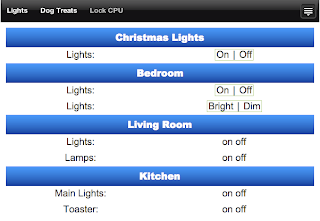
I also created my own webpage to control my lights with the look I wanted. As you can see below I also made a widget that will dim my bedroom lights. While I optimized this page to my liking, all that is required to have your own control page is to save the script in a text file and save it with an html extension.

Wednesday, December 3, 2008

Iphone as a Universe Controller: Part 1

Why have a universal remote control when you can have a universe controller? I was fortunate enough to get to beta test some of ioBridge's forthcoming hardware. Their hardware lets you connect just about anything to the internet. The possibilites with these things are just about limitless. I am convinced I can control just about anything in my house with this little board and my iPhone. The company has a number of premade "smart boards." The modules also have input/output pins so you can get any of your microcontroller projects online. I wanted to put together a few simple progects based on their smart boards. I got a x10, light sensor, and a servo smart board. I made a little gizmo with each one. In this write up I'm going to talk about the gizmo I made with their servo smart board.  In my next post I'm going to demonstrate how to control you home lights. Then I will post about how the ioBridge module can be used to lock your computer and update your twitter feed automatically when you leave the office. 

I have a dog that stays home alone while I am at school. I thought it would be nice to be able to check up on my dog Cooper during the day, and even better if I could give him a delicious doggie treat. With the ioBridge module, a servo smart board, and some random parts around the house I was able to put together a dog watching, treat giver that is all controlled with my iPhone over the internet. The whole project took about an hour and because of iobridge's simple internet interface no programing was required. 

Here is a video (youtube link) of the finished project. Below the video are my detailed instruction about the project.


Finished project in action

Here's what I used:
ioBridge I/O module
ioBridge servo smart board
servo
old CD spindle case
cardboard scrap
large syringe plunger
scrap wood
webcam (just used for visual confirmation that treat was delievered)

ioBridge servo smart board

I started by cutting a hole in the top of the old CD case for the axel of the servo to fit through. With some scrap wood I mounted the servo above the case.

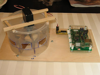
Old CD spindle case with servo attached to top. The windows in the side are for loading the dispenser with treats


I cut the plunger to a length about a quarter of an inch shorter then the interior of the old cd case. After super gluing the servo's detachable wheel to the top of the plunger I glued square cardboard scrap to half of the plunger at 45 degree angles. I made some triagnles out of wood and used them to keep each of the fins seperated by 45 degrees. While the glue dried I cut a pie shaped wedge in the board that was the same size as the wedges created by gluing the cardboard at 45 degree angles around the plunger. 

Syringe plunger with cardboard fins attached at 45 degree angles

Bottom platform with hole cut for treat to drop through


Once the glue dried I attached the plunger to the servo and connected the servo to the ioBridge I/O modeule via the servo smart board.

View of bottom of housing with plunger assembly attached to servo

Assembled device

I followed the simple ioBridge instructions for getting their board online for the first time. Using the ioBridge web interface it was simple to create a widget that controlled the servo. At the end of the widget wizard it automatically saved the buttons that controlled the position of the servo in my ioBridge dashboard (the dashboard is your home page once you log into the ioBridge website). The wizard also outputs javascript incase you want to embed the controls in your own page as I did. 

Screen shot of widget builder 

With all the javascript their site gave me it was no time before I had a webpage that I could access from my iPhone. I could have just pasted the javascript they gave me into notepad and saved it as an html and had controls that would control my device, but I wanted a little something more. I optimized it to be viewed on my iPhone and embedded a feed from a streaming webcam I placed over Cooper's kennel. Now I could see what my dog is up to when I'm away. I saved the website to my iPhone's home screen, and in less than an hour and a half from starting the project I had a web app on my phone from which I could view my dog and give him delicious, steak flavored treats. 


Icon on iPhone home screen and then view of the web app I created using the ioBridge generated javascript. The picture of my dog is from a streaming webcam.


Wednesday, February 6, 2008

Is this really upside down?

I love this type of Colgate toothpaste. The smaller size is great for
having to carry down the hall to brush my teeth after lunch at work
and was perfect for when I lived in the dorms.

I am a little curious, however, the designers of the bottle didn't
take gravity into effect. Seems to me the bottle should have been
designed to have the opening on the bottom. I always leave mine upside
down and in fact every time I see one of these in some one's bathroom
they got theirs turned on its head too.

Monday, January 28, 2008

The same ol same ol


While eating lunch, I noticed something. People really don't like change. They pretty much always do whatever they've always done no matter if the circumstances change. As I ate lunch the above rope, rat maze to funnel people to where they order was empty. I was surprised to notice as almost everyone came in they went out of their way to go through the maze instead of just walking up to the man waiting to take their order.